Technologies
An Innovative 3D Testing Ecosystem
We tested and selected the most innovative technologies we could find that support each other and work symbiotically.
result based
Next-Generation Product Testing and Measurement
Trusted by Fortune 500 companies across a dozen industries.

Digital Image Correlation (DIC)
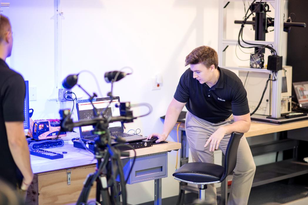
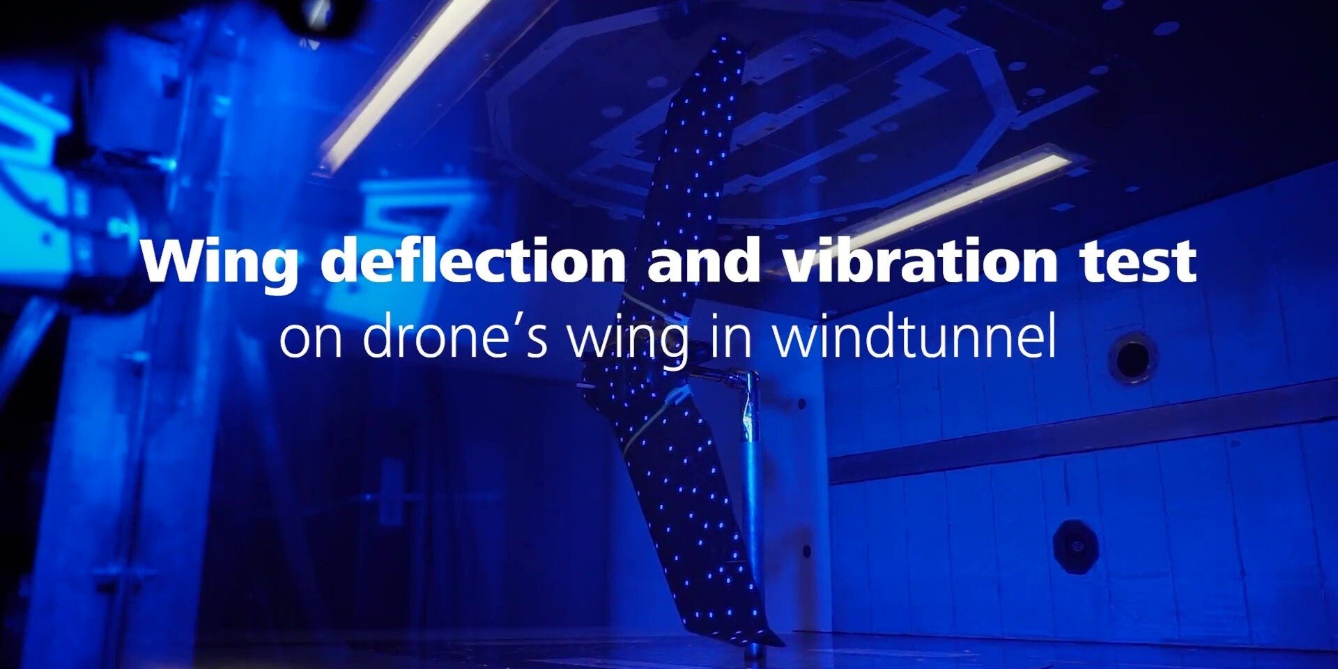
Non-contact measuring technique based on Digital Image Processing. DIC is capable of mapping 3D coordinates and evaluating displacement and strain maps on the surface of measured samples. DIC uses a stochastic pattern and/or point markers to track the surface of the materials with subpixel accuracy.
This technique can be used for a wide range of applications in materials research and component testing to analyze the static and dynamic behaviors of specimens. The full-field strain map generated by the DIC algorithm is commonly used to replace strain gauges and other traditional sensors for simulation (FEA) validation.
Photogrammetry
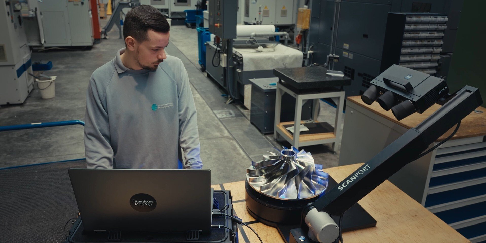
The ZEISS INSPECT software is used to analyze the high-resolution images captured by our various measurement systems, including ARAMIS, TRITOP, and ARGUS. Features such as reference points, contrast lines, and adapters are determined quickly and accurately. They are displayed in the software, including the calculated 3D coordinates. Measure and inspect not only small components but also larger parts like fuselage, trains, ships, and wind power units.
The basic software functions include capturing measurement points and processing them to model 3D point clouds as well as monitoring image quality. Tools such as CAD data import, the import of measurement plans, alignment, point deviations from CAD, calipers, angles and diameters, vector fields, GD&T analysis and reporting are available for the purpose of quality control and results analysis.
The local coordinate system in the software makes it possible to perform local or drawing-based evaluations. Hence, the dimensioning within a coordinate system is possible, standardized GD&T position analysis can be combined easily with local coordinate analysis in the same reference system and complex alignment strategies can be implemented. The local coordinate systems also form the basis for six degrees of freedom analysis.
A timeline integrated in the graphical interface supports the management of multi-stage projects, for example in statistical process control (SPC) and deformation analysis.
The software user can switch back and forth between stages within a trend project or display relevant/defined stage areas exclusively.
TRITOP Professional offers optimal orientation during measurements with its image mapping and 3D views. In addition, image mapping also allows fast and easy project navigation during analysis. Individual color-coded CAD deviations and vector displacements can be visualized easily within the color images. So that operators can work with a specific image during all work phases, an image from one stage can be displayed through several stages in TRITOP multiphase projects. Image mapping is therefore one supporting element in the presentation of results.
ZEISS Correlate Software
Free evaluation software for 3D testing to get started today
Computed Tomography (CT)
This technique is mostly known in the medical field to measure inside the body. It is gaining momentum in the manufacturing and testing markets as a non-destructive method appropriate for accurately measuring the inside of components. Based on X-Ray imaging, the CT software assembles images taken from different angles into a 3D model of the object measured. The resulting model is a 3D image where each voxel (pixels in 3D) contains information on the density of the material. A meshing algorithm is then used to separate the densities into regions and polygonize the surfaces into meshes. Metrology inspection tools are used to measure the dimensions of these surfaces, just like with a 3D scanner. The possibilities of inspections are then virtually infinite, from CAD comparison, GD&T, or trend analysis to FEA validation.
This technique can be used for a wide range of applications:
- Injection molding plastic parts inspection
- Additive manufacturing parts
- Porous materials inspection
- Biomedical components
Thermography
ARAMIS can be synchronized with a thermal imaging camera to capture temperature information. The temperature data can be imported, aligned, and mapped directly to the inspection and can then be used with other measurement data and be displayed by itself for 3-dimensional viewing. Each thermal pixel is projected onto the corresponding point of the surface mesh. The mapped values can then be inspected the same as any other ARAMIS inspection, finding maximums, minimums, averages, placing discrete points, and section lines across the data.
When it comes to thermal cameras, we rely on the best suppliers in the industry: InfraTec GmbH, Telops, and FLIR Systems Inc. Each of these suppliers has unique benefits in the thermal camera market, allowing us to give you the perfect camera for your specific application such as:
- Microelectronics testing
- Injection molding plastic parts inspection
- Additive manufacturing
- Porous materials inspection
- Biomedical components


